
The Complete Beginner’s Guide to the HC-SR501 PIR Motion Sensor

The Complete Beginner's Guide to the HC-SR501 PIR Motion Sensor

Have you ever wondered how automatic lights know when you’re approaching? Or how security systems detect when someone enters a room? The magic happens thanks to a clever little device called a PIR sensor! Today, we’ll explore one of the most popular and beginner-friendly motion sensors: the HC-SR501 PIR Infrared Motion Sensor.

What is a PIR Sensor?

PIR stands for Passive Infrared. Think of it as an electronic “eye” that can “see” heat instead of light. Everything around us that’s warmer than absolute zero (including you!) gives off invisible heat energy called infrared radiation. The warmer something is, the more infrared radiation it emits.

The HC-SR501 is called “passive” because it doesn’t send out any signals—it just sits there quietly “listening” for changes in the heat patterns around it. When something warm (like a person or pet) moves within its detection area, it notices the change and triggers an output signal.

How Does the HC-SR501 Work?

The Science Made Simple: Inside the HC-SR501 is a special component called a pyroelectric sensor with two sensing windows. When everything in the room is still, both windows detect the same amount of background heat. But when you walk by, your body heat affects one window more than the other, creating a difference that the sensor interprets as motion.

The White Dome: That distinctive white plastic dome on top isn’t just for protection—it’s actually a special lens called a Fresnel lens. This lens acts like multiple magnifying glasses working together to expand the sensor’s field of view and focus infrared radiation from different areas onto the tiny sensor inside.

Key Specifications

Here are the important numbers you need to know:

  • Detection Range: 3 to 7 meters (10 to 23 feet) – adjustable
  • Detection Angle: About 110-120 degrees
  • Operating Voltage: 4.5V to 20V DC (5V recommended for Arduino)
  • Output Signal: 3.3V when motion detected, 0V when idle
  • Current Consumption: Less than 50 microamps (very power efficient!)
  • Warm-up Time: 30-60 seconds when first powered on

Understanding the HC-SR501 Layout

Three Main Pins:

  • VCC: Power input (connect to 5V)
  • GND: Ground connection
  • OUT: Signal output (connects to your microcontroller)

Two Adjustment Potentiometers (the orange knobs):

  1. Sensitivity Adjustment (Sx):
    • Controls how far the sensor can detect motion
    • Turn clockwise: Increases range (up to 7 meters)
    • Turn counterclockwise: Decreases range (down to 3 meters)
  2. Time Delay Adjustment (Tx):
    • Sets how long the output stays HIGH after detecting motion
    • Turn clockwise: Longer delay (up to 5 minutes)
    • Turn counterclockwise: Shorter delay (as low as 5 seconds)

Trigger Mode Jumper:

  • H Position (Repeating Trigger): Sensor continues to detect motion while you’re in range
  • L Position (Single Trigger): Sensor triggers once, then waits for the delay period to finish

Getting Started: Your First Test

What You’ll Need:

  • HC-SR501 sensor
  • Arduino Uno (or any 5V microcontroller)
  • LED and 220-ohm resistor
  • Breadboard and jumper wires
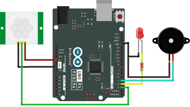
Simple Wiring:

  1. Connect VCC to Arduino 5V
  2. Connect GND to Arduino GND
  3. Connect OUT to Arduino digital pin 2
  4. Connect LED through resistor to pin 13

Basic Code:

int pirPin = 2;    // PIR sensor connected to pin 2

int ledPin = 13;   // LED connected to pin 13

void setup() {

  pinMode(pirPin, INPUT);

  pinMode(ledPin, OUTPUT);

  Serial.begin(9600);

  // Wait for sensor to warm up

  Serial.println("Warming up sensor...");

  delay(60000);  // Wait 60 seconds

  Serial.println("Sensor ready!");

}

void loop() {

  if (digitalRead(pirPin) == HIGH) {

    digitalWrite(ledPin, HIGH);

    Serial.println("Motion detected!");

  } else {

    digitalWrite(ledPin, LOW);

  }

  delay(100);

}

Important Timing Considerations

Warm-up Period: When you first power on the HC-SR501, it needs 30-60 seconds to adjust to the room’s baseline infrared levels. During this time, it might give false readings, so always include this delay in your code.

Blocking Time: After the sensor output goes from HIGH to LOW, there’s a built-in 2.5-second “blocking period” where the sensor won’t detect any motion. This is normal behavior and prevents false triggering.

Practical Applications

Home Automation:

  • Automatic hallway lights
  • Smart bathroom fans
  • Energy-saving room lighting

Security Projects:

  • Simple alarm systems
  • Visitor detection for doorbells
  • Wildlife monitoring cameras

Fun Projects:

  • Halloween decorations that activate when someone approaches
  • Pet monitoring systems
  • Interactive art installations

Tips for Success

Placement Matters:

  • Mount the sensor horizontally for best human detection
  • Avoid pointing it directly at heat sources (radiators, sunlight)
  • Keep it away from moving objects like curtains or plants

Fine-Tuning:

  • Start with sensitivity in the middle position
  • Set time delay to at least 3 seconds for Arduino projects
  • Use “H” (repeating trigger) mode for most applications

Troubleshooting:

  • If it’s too sensitive, turn the sensitivity knob counterclockwise
  • If it’s not detecting motion, check your wiring and increase sensitivity
  • Remember the warm-up period—be patient!

Advanced Features (Optional)

The HC-SR501 has solder pads for two optional components:

  • RL Pad: Add a light-dependent resistor (LDR) to make the sensor only work in darkness
  • RT Pad: Add a thermistor for temperature compensation

These are advanced modifications that most beginners won’t need.

Ready to Build Something Amazing?

The HC-SR501 PIR sensor is an excellent starting point for motion detection projects. It’s reliable, affordable, and works right out of the box with minimal setup. Whether you’re building a simple automatic light or a complex home automation system, this sensor provides the motion detection foundation you need.

Next Steps:

  • Try the basic test circuit above
  • Experiment with the sensitivity and timing adjustments
  • Combine it with other sensors and outputs for more complex projects
  • Check out online communities for project inspiration

The world of motion sensing awaits—now get out there and start building!

Servo Motors: A Beginner’s Complete Guide

Servo Motors: A Beginner's Complete Guide

If you’ve ever wondered how robots move with such precision, or how remote-controlled cars can steer so accurately, chances are you’re looking at servo motors in action. These remarkable devices are everywhere in our modern world, yet many people don’t fully understand what they are or how they work.

What Exactly is a Servo Motor?

Think of a servo motor as a regular electric motor with a built-in brain. While a standard motor just spins continuously when you apply power, a servo motor can rotate to a specific angle and hold that position with incredible accuracy. It’s like the difference between a spinning wheel and a precise robotic arm that can point exactly where you tell it to.

The word “servo” comes from the Latin word “servus,” meaning servant. That’s essentially what these motors do – they serve your commands by moving to exact positions and staying there until you tell them otherwise.

The Anatomy of a Servo Motor

Every servo motor contains three main components working together:

The DC Motor provides the actual movement and power. This is the muscle of the system.

The Control Circuit acts as the brain, processing your commands and determining how much the motor needs to move.

The Feedback System serves as the eyes and ears, constantly monitoring the motor’s current position using a potentiometer or encoder.

These three components work together in what engineers call a “closed-loop system.” The motor moves, the feedback system reports the current position, and the control circuit makes adjustments to reach the exact target position.

How Do Servo Motors Actually Work?

Imagine you’re trying to park your car in a tight space. You turn the wheel, check your position, adjust, check again, and repeat until you’re perfectly positioned. Servo motors work similarly, but they do this hundreds of times per second.

Here’s the process:

  1. You send a control signal telling the servo where to go
  2. The control circuit compares this target with the current position
  3. If there’s a difference, the motor starts moving in the right direction
  4. The feedback system continuously reports the current position
  5. When the motor reaches the target, it stops and holds that position

This entire process happens so quickly that the movement appears smooth and precise to our eyes.

Types of Servo Motors You’ll Encounter

Standard Servos are the most common type, typically rotating about 180 degrees. These are perfect for applications like steering mechanisms or camera mounts.

Continuous Rotation Servos can spin full circles like regular motors, but you can control their speed and direction precisely. Think of them as regular motors with better manners.

Linear Servos move in straight lines instead of rotating, perfect for applications like automatic door locks or precise positioning systems.

Where You’ll Find Servo Motors

Servo motors are surprisingly common in everyday life:

Remote-Controlled Toys use tiny servos for steering cars, moving robot arms, and controlling airplane flaps.

Industrial Automation relies heavily on servo motors for assembly lines, packaging machines, and robotic manufacturing.

Automotive Systems use servos for power steering, throttle control, and various adjustment mechanisms.

Home Appliances incorporate servos in everything from washing machine door locks to automatic pet feeders.

Medical Equipment depends on servo precision for surgical robots, MRI machines, and patient positioning systems.

Why Choose Servo Motors?

The main advantage of servo motors is their precision. While a regular motor might be accurate to within several degrees, a good servo motor can position itself to within fractions of a degree. This precision comes with excellent holding power – once positioned, a servo motor will maintain its position even against external forces.

Servo motors also offer excellent speed control and can accelerate or decelerate smoothly, making them ideal for applications requiring gentle, precise movements.

Getting Started with Servo Motors

If you’re interested in experimenting with servo motors, they’re surprisingly accessible for beginners. Small hobby servos cost just a few dollars and can be controlled with simple microcontrollers like Arduino or Raspberry Pi.

Most servo motors use a standard three-wire connection: power, ground, and control signal. The control signal is typically a PWM (Pulse Width Modulation) signal that tells the servo where to position itself.

Common Applications for Beginners

Robotic Arms are popular first projects, allowing you to create a simple pick-and-place mechanism.

Camera Tracking Systems can automatically follow subjects or create smooth panning effects.

Automated Blinds or Curtains provide a practical home automation project.

Pet Feeders can dispense food at scheduled times with precise portion control.

Things to Keep in Mind

When working with servo motors, remember that they consume power continuously while holding position. This is different from stepper motors, which only use power when moving.

Also, servo motors work best within their specified range of motion. Trying to force them beyond their limits can damage the internal feedback mechanism.

The Future of Servo Motors

As technology advances, servo motors are becoming smarter and more efficient. Modern servos can communicate digitally, provide detailed status information, and even adapt their performance based on the load they’re carrying.

Whether you’re building your first robot or just curious about the technology around you, understanding servo motors opens up a world of possibilities for precise, controlled movement in countless applications.

Ready to Get Started?

Servo motors represent one of the most accessible entry points into precision motion control. With their combination of accuracy, reliability, and ease of use, they’re perfect for both learning and practical applications. The next time you see something moving with remarkable precision, there’s a good chance a servo motor is making it happen.

MPU-6050 Accelerometer & Gyroscope: A Complete Beginner’s Guide

MPU-6050 Accelerometer & Gyroscope: A Complete Beginner's Guide

The MPU-6050 is one of the most popular motion sensors in the world of electronics and robotics. If you’ve ever wondered how your smartphone knows which way you’re tilting it, or how drones stay stable in the air, chances are there’s something very similar to the MPU-6050 inside doing the work!

What is the MPU-6050?

The MPU-6050 is a Micro Electro-Mechanical Systems (MEMS) which consists of a 3-axis Accelerometer and 3-axis Gyroscope inside it. Think of it as a tiny electronic device that can sense how something is moving and tilting in 3D space.

In simple terms:

  • Accelerometer: Detects how fast something is speeding up or slowing down
  • Gyroscope: Detects how fast something is rotating or spinning
  • 6-axis: 3 axes for acceleration + 3 axes for rotation = 6 total measurements

At the core of the module is a low-power, low-cost 6-axis MotionTracking chip – MPU6050 – that integrates a 3-axis gyroscope, 3-axis accelerometer, and a Digital Motion Processor (DMP) into a tiny 4mm x 4mm package.

Key Features & Specifications

Physical Characteristics

  • Size: Just 4mm x 4mm x 0.9mm (incredibly tiny!)
  • Package: 24-pin QFN (Quad Flat No-leads)
  • Power: Works with 3.3V to 5V (perfect for Arduino projects)
  • Communication: Uses I2C protocol (only needs 2 wires for data!)

Accelerometer Capabilities

The MPU-6050 has an on-chip accelerometer that can measure acceleration over four programmable full scale ranges of ±2g, ±4g, ±8g, and ±16g.

What does this mean?

  • ±2g: Perfect for detecting gentle movements (like tilting your phone)
  • ±16g: Can handle very fast movements (like detecting a car crash)
  • 16-bit resolution: Extremely precise measurements

Gyroscope Capabilities

The MPU-6050 has an on-chip gyroscope that can measure angular rotation over four programmable full scale ranges of ±250°/s, ±500°/s, ±1000°/s, and ±2000°/s.

What does this mean?

  • ±250°/s: Detects slow rotations (like slowly turning your head)
  • ±2000°/s: Detects very fast spins (like a spinning top)
  • 16-bit resolution: Super accurate rotation measurements

Additional Features

  • Temperature sensor: Can measure temperatures from -40 to 85°C with a ±1°C accuracy
  • Digital Motion Processor (DMP): A tiny computer inside that can do complex calculations
  • Low power: Consumes less than 3.6mA during measurements and only 5μA when idle
  • Shock resistant: Can withstand 10,000g shock

How Does It Work?

The Accelerometer

To understand how accelerometers work, imagine a ball inside a 3D cube. Assuming that the cube is in outer space, where everything is weightless, the ball will simply float in the center of the cube.

But on Earth, gravity pulls the ball down. The MPU-6050’s accelerometer works similarly – it has tiny masses inside that move when the sensor accelerates or tilts. These movements are detected and converted into electrical signals.

The Three Axes:

  • X-axis: Left and right movement
  • Y-axis: Forward and backward movement
  • Z-axis: Up and down movement

The Gyroscope

The gyroscope measures rotational velocity or rate of change of the angular position over time, along the X, Y and Z axis. It uses MEMS technology and the Coriolis Effect for measuring.

Think of it like this:

  • When you turn your head left or right (like saying “no”) – that’s rotation around the Z-axis
  • When you nod your head up and down (like saying “yes”) – that’s rotation around the X-axis
  • When you tilt your head side to side – that’s rotation around the Y-axis

Common Applications

The MPU-6050 is incredibly versatile and used in many everyday devices:

Consumer Electronics

  • Smartphones & Tablets: Screen rotation, step counting, gaming controls
  • Gaming Controllers: Motion-controlled games like Nintendo Wii
  • Fitness Trackers: Counting steps, detecting activities
  • VR Headsets: Tracking head movements

Robotics & DIY Projects

  • Drones: Keeping them stable and level in flight
  • Self-balancing robots: Like those two-wheeled robots that don’t fall over
  • Gesture control: Making robots respond to hand movements
  • Security systems: Detecting when something moves

Automotive

  • Electronic Stability Control: Preventing cars from skidding
  • Airbag deployment: Detecting crashes
  • Anti-theft systems: Detecting if a car is being moved

Working with Arduino

The MPU-6050 is extremely popular with Arduino users because it’s:

Easy to Connect

You only need 4 wires:

  • VCC: Power (3.3V or 5V)
  • GND: Ground
  • SDA: Data line for I2C communication
  • SCL: Clock line for I2C communication

Simple to Program

Thanks to the library developed by Jeff Rowberg, getting started is straightforward. You can have basic motion detection working in just a few lines of code!

Versatile Projects

Popular beginner projects include:

  • Motion detection alarm: Triggers when something moves
  • Digital level: Shows if a surface is perfectly flat
  • Step counter: Counts your steps as you walk
  • Tilt-controlled LED: LEDs that change as you tilt the sensor

Understanding the Data

Raw vs. Processed Data

The MPU-6050 gives you two types of data:

Raw Data:

  • Direct readings from the sensors
  • Numbers like +15454 for accelerometer or +2500 for gyroscope
  • Need to be converted to meaningful units

Processed Data:

  • Acceleration along the X axis = (Accelerometer X axis raw data/16384) g
  • Angular velocity along the X axis = (Gyroscope X axis raw data/131) °/s
  • Much easier to understand and work with

Common Measurements

  • Roll: Rotation like an airplane banking left or right
  • Pitch: Rotation like an airplane’s nose going up or down
  • Yaw: Rotation like a compass needle spinning

Advantages for Beginners

Why Choose the MPU-6050?

  1. Affordable: Usually costs under $5
  2. Well-documented: Tons of tutorials and examples online
  3. Arduino-friendly: Extensive library support
  4. Versatile: Can be used in many different projects
  5. Reliable: The MPU-6050™ parts are the world’s first MotionTracking devices designed for the low power, low cost, and high-performance requirements

Learning Benefits

  • I2C Communication: Learn how devices talk to each other
  • Sensor Fusion: Combine accelerometer and gyroscope data for better accuracy
  • Real-time Processing: Work with continuous data streams
  • 3D Thinking: Understand motion in three-dimensional space

Getting Started Tips

For Complete Beginners

  1. Start Simple: Begin with basic examples that just print sensor values
  2. Understand the Axes: Spend time figuring out which way is X, Y, and Z
  3. Calibration: Learn how to account for sensor errors and drift
  4. Filtering: Understand how to smooth noisy sensor data

Common Challenges

  • Noise: Sensor readings can be jumpy – filtering helps
  • Drift: Gyroscope readings tend to drift over time
  • Orientation: Getting confused about which axis is which
  • Units: Remember to convert raw data to meaningful units

Conclusion

The MPU-6050 is an incredible sensor that opens up a world of motion-sensing possibilities. Whether you’re building your first Arduino project or dreaming of creating the next generation of smart devices, understanding how to work with accelerometers and gyroscopes is an essential skill.

From robotics to wearables, the GY-521’s versatility allows it to be used in a wide range of projects. With its combination of affordability, capability, and ease of use, the MPU-6050 is the perfect sensor to start your journey into the fascinating world of motion detection and inertial measurement.

The key to success with the MPU-6050 is to start simple, experiment often, and gradually build up to more complex projects. Before you know it, you’ll be creating amazing motion-controlled devices that seemed impossible when you first started!


Ready to get started? Pick up an MPU-6050 module, download the Arduino IDE, and begin exploring the exciting world of motion sensing today!

ESP32 Beginner’s Guide: Everything You Need to Know

ESP32 Beginner's Guide: Everything You Need to Know

What is the ESP32?

The ESP32 is like a tiny computer on a chip that can connect to the internet and control electronic devices. Think of it as a super-smart brain that can wirelessly communicate with other devices while being small enough to fit in your palm. It’s made by a Chinese company called Espressif Systems and is incredibly popular among hobbyists, students, and professional engineers.

Why is the ESP32 Special?

Built-in Connectivity

  • Wi-Fi: Can connect to your home internet just like your phone or laptop
  • Bluetooth: Can communicate with phones, headphones, and other Bluetooth devices
  • Dual-mode: Can use both Wi-Fi and Bluetooth at the same time

Powerful Processing

  • Dual-core processor: Has two “brains” that can work simultaneously (some versions have just one)
  • Speed: Runs at up to 240 MHz – that’s really fast for such a small chip
  • Memory: Has built-in storage for your programs and data

Key Technical Specifications (In Simple Terms)

The Brain (Processor)

  • Cores: 1 or 2 processors (depending on the model)
  • Speed: Up to 240 MHz (imagine a car engine that can rev up to 240,000 RPM)
  • Architecture: 32-bit Xtensa LX6 (this is the “language” the processor speaks)

Memory (Storage)

  • RAM: 520 KB (for temporary data while running)
  • ROM: 448 KB (permanent storage for basic functions)
  • Flash Memory: 0-4 MB depending on model (where your programs live)

Input/Output Pins

  • Total GPIO Pins: 34 pins you can connect things to
  • Analog Inputs: 18 pins that can read sensors (like temperature or light)
  • Digital Outputs: Can control LEDs, motors, displays, etc.
  • Special Functions: SPI, I2C, UART for talking to other devices

Power Requirements

  • Voltage: 2.3V to 3.6V (usually powered by 3.3V)
  • Current: Varies from 5 µA (sleeping) to 240 mA (full power with Wi-Fi)

Different ESP32 Variants

Just like cars come in different models, ESP32 comes in several versions:

ESP32-D0WD-V3 (Most Common)

  • Dual-core processor
  • No built-in flash memory
  • Most flexible option

ESP32-U4WDH

  • Dual-core processor
  • 4 MB built-in flash memory
  • Good for projects that need lots of storage

ESP32-D0WDR2-V3

  • Dual-core processor
  • 2 MB built-in PSRAM (extra memory)
  • Great for memory-intensive applications

What Can You Connect to the ESP32?

Sensors

  • Temperature and humidity sensors
  • Motion detectors
  • Light sensors
  • Pressure sensors
  • GPS modules

Outputs

  • LEDs and LED strips
  • Motors and servos
  • Displays (LCD, OLED)
  • Speakers and buzzers
  • Relays to control appliances

Communication

  • Other ESP32 boards
  • Smartphones via Bluetooth
  • Internet services via Wi-Fi
  • SD cards for data storage

Power Modes (Battery Life Features)

The ESP32 is smart about power usage:

Active Mode

  • All systems running: ~95-240 mA
  • Wi-Fi and Bluetooth working
  • All processors active

Light Sleep

  • Processor paused: ~0.8 mA
  • Can wake up quickly
  • Wi-Fi connection maintained

Deep Sleep

  • Almost everything off: ~10 µA
  • Only wake-up timer running
  • Can run for months on battery

Hibernation

  • Bare minimum power: ~5 µA
  • Can run for years on battery
  • Only basic wake-up functions

Development Boards vs. Bare Chips

Bare ESP32 Chip

  • Just the processor
  • Requires additional components
  • Difficult for beginners

Development Boards (Recommended for Beginners)

  • ESP32 chip plus supporting components
  • USB connection for programming
  • Pin headers for easy connections
  • Built-in voltage regulation
  • Reset and boot buttons

Popular boards include:

  • ESP32 DevKit V1
  • ESP32-WROOM-32
  • ESP32-WROVER

Programming the ESP32

Arduino IDE (Easiest for Beginners)

  • Familiar environment
  • Lots of tutorials and examples
  • Large community support

ESP-IDF (Advanced)

  • Official development framework
  • More powerful features
  • Steeper learning curve

MicroPython

  • Python programming language
  • Good for rapid prototyping
  • Easier than C++ for some people

Common Project Ideas

Beginner Projects

  • Blinking LED (Hello World of electronics)
  • Temperature monitoring
  • Smart doorbell
  • Plant watering reminder

Intermediate Projects

  • Home automation system
  • Weather station
  • Security camera
  • IoT sensor network

Advanced Projects

  • Voice-controlled assistant
  • Autonomous robot
  • Machine learning applications
  • Industrial monitoring systems

Advantages Over Other Microcontrollers

Compared to Arduino Uno

  • Built-in Wi-Fi and Bluetooth
  • Much faster processor
  • More memory
  • Lower cost

Compared to Raspberry Pi

  • Lower power consumption
  • Better for real-time applications
  • More robust for embedded projects
  • Lower cost

Things to Consider

Learning Curve

  • More complex than basic Arduino
  • Requires understanding of networking
  • More configuration options

Power Management

  • Needs stable power supply
  • Can consume significant current
  • Requires careful design for battery projects

Pin Limitations

  • Some pins have special functions
  • Not all pins can be used freely
  • Input-only pins (GPIO 34-39)

Getting Started Tips

  1. Start with a development board, not the bare chip
  2. Use Arduino IDE for your first projects
  3. Begin with simple projects before adding Wi-Fi
  4. Join online communities for help and inspiration
  5. Read datasheets for technical details
  6. Practice with sensors before building complex systems

Cost Considerations

  • Bare ESP32 chip: $2-5
  • Development boards: $5-15
  • Very affordable compared to capabilities
  • Great value for IoT projects

Conclusion

The ESP32 is an incredibly powerful and versatile microcontroller that brings internet connectivity to your projects at an affordable price. While it has a steeper learning curve than basic microcontrollers, its capabilities make it perfect for modern IoT applications. Whether you’re a hobbyist wanting to automate your home, a student learning embedded systems, or an engineer prototyping commercial products, the ESP32 offers the connectivity and processing power you need.

Start with simple projects, learn gradually, and before you know it, you’ll be creating amazing connected devices that seemed impossible just a few years ago!

DHT11 vs DHT22: A Beginner’s Guide to Temperature and Humidity Sensors

DHT11 vs DHT22: A Beginner's Guide to Temperature and Humidity Sensors

If you’re just starting with electronics projects and want to measure temperature and humidity, you’ve probably come across the DHT11 and DHT22 sensors. These are two of the most popular sensors in the maker community, and for good reason – they’re affordable, easy to use, and perfect for beginners. But which one should you choose? Let’s break it down in simple terms.

What Are These Sensors?

Both the DHT11 and DHT22 are digital sensors that can measure two things:

  • Temperature (how hot or cold it is)
  • Humidity (how much moisture is in the air)

Think of them as tiny weather stations that you can connect to your Arduino, Raspberry Pi, or other microcontroller projects. The best part? They come pre-calibrated from the factory, so they’re ready to use right out of the box!

How Do They Work?

Inside each sensor, there are two main components working together:

For Humidity Detection:

  • A special material (like a polymer) sits between two metal plates
  • When there’s more moisture in the air, this material absorbs water and changes its electrical properties
  • The sensor measures this change to determine humidity levels

For Temperature Detection:

  • A component called an NTC thermistor changes its electrical resistance as temperature changes
  • When it gets warmer, the resistance decreases; when it gets cooler, the resistance increases
  • The sensor measures this resistance change to calculate temperature

DHT11: The Budget-Friendly Option

Specifications:

  • Temperature Range: 0°C to 50°C (32°F to 122°F)
  • Temperature Accuracy: ±2°C (±3.6°F)
  • Humidity Range: 20% to 80%
  • Humidity Accuracy: ±5%
  • Reading Speed: 1 reading per second
  • Price: Usually $2-5

Best For:

  • Indoor projects like home weather stations
  • Learning and educational purposes
  • Projects where high precision isn’t critical
  • Budget-conscious makers

Pros:

  • Very affordable
  • Smaller size
  • Faster readings (1 per second)
  • Perfect for beginners
  • Low power consumption

Cons:

  • Limited temperature range
  • Lower accuracy
  • Can’t measure very high or low humidity levels

DHT22: The Performance Upgrade

Specifications:

  • Temperature Range: -40°C to 125°C (-40°F to 257°F)
  • Temperature Accuracy: ±0.5°C (±0.9°F)
  • Humidity Range: 0% to 100%
  • Humidity Accuracy: ±2-5%
  • Reading Speed: 1 reading every 2 seconds
  • Price: Usually $5-10

Best For:

  • Outdoor weather monitoring
  • Professional or commercial applications
  • Projects requiring high accuracy
  • Extreme environment monitoring

Pros:

  • Much wider temperature range
  • Better accuracy for both temperature and humidity
  • Can measure full humidity range (0-100%)
  • More reliable for long-term projects

Cons:

  • More expensive
  • Slightly larger
  • Slower readings (every 2 seconds)

Side-by-Side Comparison

FeatureDHT11DHT22
PriceLower ($2-5)Higher ($5-10)
Temperature Range0°C to 50°C-40°C to 125°C
Temperature Accuracy±2°C±0.5°C
Humidity Range20% to 80%0% to 100%
Humidity Accuracy±5%±2-5%
Reading Speed1 per second1 per 2 seconds
SizeSmallerSlightly larger
Best UseIndoor, learningOutdoor, precision

Connecting and Using These Sensors

The great news is that both sensors are incredibly easy to connect:

What You Need:

  • Your sensor (DHT11 or DHT22)
  • A microcontroller (like Arduino)
  • A pull-up resistor (usually 4.7kΩ or 10kΩ)
  • Some jumper wires

Basic Connections:

  • VCC/Power: Connect to 3.3V or 5V on your microcontroller
  • GND/Ground: Connect to ground
  • Data: Connect to any digital pin on your microcontroller
  • Pull-up resistor: Connect between the data pin and power

Both sensors use the same wiring setup and are completely interchangeable – if you build a project with a DHT11, you can swap in a DHT22 later without changing any wires!

Which One Should You Choose?

Choose the DHT11 if:

  • You’re just starting with electronics
  • Your project is indoors (room temperature range)
  • You want to save money
  • You need faster readings
  • Precision isn’t critical

Choose the DHT22 if:

  • You need outdoor weather monitoring
  • Your project requires high accuracy
  • You might encounter extreme temperatures
  • You want to measure very low or high humidity
  • You’re building something for long-term use

Real-World Applications

DHT11 Projects:

  • Room temperature monitor
  • Basic home automation
  • Greenhouse monitoring (mild climates)
  • Learning exercises
  • Simple weather displays

DHT22 Projects:

  • Outdoor weather stations
  • HVAC system monitoring
  • Industrial applications
  • Scientific data logging
  • Precision climate control

Tips for Beginners

  1. Start Simple: If you’re new to electronics, begin with the DHT11 to learn the basics
  2. Library Support: Both sensors work with the same Arduino libraries, making programming easy
  3. Response Time: Remember that these sensors need time to adjust – don’t expect instant readings when conditions change
  4. Protection: If using outdoors, protect your sensor from direct rain and extreme conditions
  5. Power Supply: Use a stable 5V power supply for best performance and longer cable runs

The Bottom Line

Both the DHT11 and DHT22 are excellent choices for measuring temperature and humidity. The DHT11 is perfect for beginners and indoor projects where you want to keep costs low. The DHT22 is worth the extra cost if you need better accuracy, wider ranges, or plan to use it outdoors.

The beauty of these sensors is that they’re both beginner-friendly, well-documented, and supported by a huge community of makers. Whichever you choose, you’ll be able to start measuring environmental conditions in your projects right away!

Happy making!

Accident Detection and Alert Systemusing Vibration and GPS Modules

This project is designed to automatically detect car accidents and immediately alert emergency contacts or services with the vehicle’s location. A vibration sensor is used to detect sudden shocks or collisions. When an impact is detected, the system activates the GPS module to retrieve the vehicle’s current coordinates. These coordinates are then sent via SMS using a GSM module to predefined emergency numbers. This real-time response system ensures that help can be dispatched quickly, even if the driver is unconscious or unable to call for help. It enhances road safety and reduces emergency response time, potentially saving lives in critical situations. The system is ideal for integration in smart vehicles, especially in high-risk or remote areas.

Smart Car Parking Systemusing Ultrasonic Sensors and Arduino

This project detects available parking slots using ultrasonic sensors and displays real-time availability on an LCD or mobile app. Ideal for smart city and mall parking management.

Pesticide Sprayer Spider Robot with Grass Cutter

Modern farming faces key challenges in pesticide application and weed management due to the limitations of traditional sprayer systems. These systems often lack precision, resulting in resource wastage and environmental harm. The proposed solution introduces an autonomous robot equipped with remote control capability, allowing farmers to navigate the robot within a 5-meter range. This enables real-time oversight while maintaining a safe distance from pesticide exposure. With integrated sensors, cameras, and smart algorithms, the robot can distinguish between crops and weeds, ensuring accurate pesticide spraying only where necessary.
A front-mounted weed cutter further enhances the robot’s efficiency, allowing operators to target and eliminate unwanted weeds on the spot. This dual-functionality system reduces the need for separate manual weeding and improves overall crop care. The onboard tank provides sufficient pesticide storage for extended operation, minimizing refill frequency and increasing field coverage.